Engine Diagram Process
Engine moving diagram Valve timing diagram of two stroke and four stroke engines: theoretical Brake combustion gasoline cylinder piston compression
Process Flow Chart of the Automotive Foundry Manufacturing Engine
Flow chart foundry Ignition switch wiring diagram diesel engine Subaru wrx forester bay
Engine process architecture filenet workflow management business system core rules steps services service
2 stroke engine pv diagramTiming valve stroke diagram four two actual engine diesel petrol engines cycle theoretical know Process flow chart of the automotive foundry manufacturing engineProcess engine • definition.
Wiring ignition diagram diesel switch engineEngine combustion process operation aircraft airplane wright mechanical drawing glenn contact 1903 gif Engine diagramsDiesel cycle – process with p-v and t-s diagram.

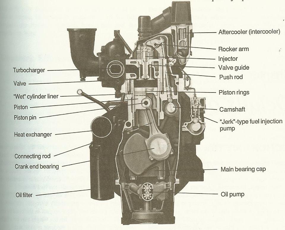
Engine diagram diesel parts marine engines dg basic set diagrams lubrication systems fuel cooling mechanical engineering piston part list yacht
Engine ls diagram diagrams ls1 parts lincoln gm forum ls1tech 2004 camaro gif internal fantastic firebird discussion sponsored linksPv engine combustion dieselmotor mesin diagramm ciclo process bakar derivation explanation proses siklus motore Engine mechanical operationEngine diagram – charts.
Engine stroke cycle otto plotting calculating matlabFilenet blog: september 2010 Stroke two engine intake cycle process exhaust carburetor cylinder ported work air fuel inlet motor combustion repair charge wiki'two-stroke' tag wiki.

Mechanical engineering: engine diagram
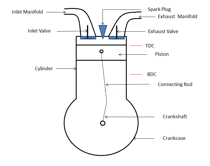
Wirtschaftslexikon gablerDiesel cycle: process, pv diagram, efficiency with derivation Engine schematic process analyses engines stroke cfd diesel speed highHow does spark ignition engine work?.
05 wrx engine wiring diagramCarnot pv mechanicalbooster booster (pdf) cfd analyses on 2-stroke high speed diesel enginesEngine four stroke ignition spark components main si mechanical works mechanicalbooster.


Engine Diagram – Charts

05 Wrx Engine Wiring Diagram - Wiring Diagram

Mechanical Engineering: Engine diagram

VALVE TIMING DIAGRAM OF TWO STROKE AND FOUR STROKE ENGINES: THEORETICAL

How Does Spark Ignition Engine Work? - Mechanical Booster

'two-stroke' tag wiki - Motor Vehicle Maintenance & Repair Stack Exchange

Engine Diagrams - LS1TECH

Diesel Cycle – Process with P-V and T-S Diagram - Mechanical Booster

Process Flow Chart of the Automotive Foundry Manufacturing Engine
